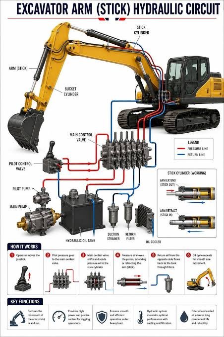
Hydraulic oil temperature rise is more than an operational annoyance. It is a reliable indicator that input energy is being converted into heat instead of useful work. When oil overheats, viscosity drops, internal leakage worsens, and seals, hoses, and valve components age faster. This guide breaks down the most common causes and provides a practical on-site diagnostic sequence for construction machinery.
Why Hydraulic Oil Temperature Climbs
Every hydraulic system generates some heat. Pump inefficiency, pressure drops across valves, flow through restrictions, and mechanical friction all consume energy and release it as heat. Normal systems dissipate this heat through reservoirs, coolers, and surface radiation. A persistent high-temperature condition means the heat input exceeds the system’s ability to reject it. The sources below are where excess heat usually enters.
1. Excessive Relief Valve or System Pressure
When a relief valve is set too high or a load-sensing signal is misadjusted, the pump may operate at higher pressure than necessary. Excess flow that cannot be used by the actuators returns to tank through the relief valve, converting pressure energy directly into heat. The relief valve itself may become hot and produce a continuous hissing or rushing sound.
Field note: If equipment action is weak, do not blindly increase pressure. First verify the actual load requirement. A cylinder or motor that struggles at normal pressure may have internal leakage or mechanical binding; raising pressure only adds heat and accelerates wear.
2. Internal Leakage in Pumps, Valves, and Cylinders
Worn pump pistons, valve spools, or cylinder piston seals allow high-pressure oil to bypass to the low-pressure side through internal clearances. That bypassed oil does no useful work—its pressure energy becomes heat. Internal leakage often shows up as slow actuator movement, reduced holding force, and elevated housing temperatures on the leaking component.
Common contributors include abrasive wear from contaminated oil, degraded seals, scored bores, and excessive clearances after long service. Changing the oil without correcting the leakage path will not solve the overheating problem.
3. High Flow Resistance in Lines and Valves
Undersized hoses, excessive fittings and elbows, small valve ports, and clogged filters all create pressure drop. The energy lost across a restriction becomes heat. A filter bypass indicator, a crushed hose, or a hot fitting can point to a restriction.
During system design or component replacement, match hose and valve sizes to the required flow rate. On existing machines, inspect filters, check for kinked or flattened hoses, and verify that quick couplings are fully engaged and correctly sized.
4. Cooling System Inefficiency
Water-cooled heat exchangers can suffer from low coolant flow, scale buildup, or blocked water passages. Air-cooled oil coolers lose performance when fins are clogged with dust, fan speed is low, or airflow is obstructed. If the machine runs hot in summer but normal in winter, the cooling system may be undersized for the ambient conditions.
Treat the cooler as a critical system component, not an accessory. Inspect it during routine maintenance and ensure that both oil and cooling medium flow paths are clean.
5. Oil Viscosity Mismatch
Oil that is too thick increases pump suction resistance and line losses, especially during cold start. Oil that is too thin increases internal leakage and reduces film strength when hot. Many machines that start fine in winter become sluggish in summer because viscosity drops as temperature rises, allowing more bypass and heat generation.
Always use the viscosity grade recommended by the equipment manufacturer for the operating temperature range. When ambient conditions change significantly, consider whether a seasonal viscosity adjustment is appropriate.
On-Site Diagnostic Sequence
Use the following order to avoid guessing and unnecessary component replacement. The goal is to identify where heat is being generated and whether the cooling path is adequate.
Step A: Check System Pressure and Relief Valve Behavior
- Read the system pressure gauge during normal operation and under load.
- Compare the observed pressure with the setting specified for the machine and the actual load needs.
- Listen at the relief valve or main control valve for a continuous rush of oil, which indicates continuous bypass.
- If pressure is higher than required, reduce it only after confirming that actuators and loads are in good condition.
Step B: Inspect Cooler and Filters
- For air-cooled systems, check for clogged fins, damaged fan blades, and proper fan rotation.
- For water-cooled systems, verify coolant flow, look for scale, and measure inlet/outlet temperature difference if possible.
- Check filter condition indicators or differential pressure gauges. Replace clogged filters according to the maintenance schedule.
- Inspect all hoses for kinks, crushing, or local hot spots that indicate restriction.
Step C: Measure Local Surface Temperatures
Use an infrared thermometer or thermal camera to scan the pump housing, valve block, cylinders, and major lines. A component that is significantly hotter than surrounding components often indicates internal leakage or a local restriction. Focus troubleshooting on the hottest accessible point.
Step D: Evaluate Oil Condition and Internal Leakage
If pressure, cooling, and filters are acceptable but temperature remains high, internal leakage is likely. Observe actuator drift under load, listen for pump noise changes under pressure, and consider an oil sample analysis for wear metals and viscosity. In many cases, a pump or valve bench test is needed to confirm leakage beyond acceptable limits.
Safety note: Hydraulic oil and components can reach temperatures that cause severe burns. Always shut down the machine, relieve system pressure, and follow lockout/tagout procedures before touching lines, fittings, or components. Use heat-resistant gloves and eye protection when inspecting hot systems.
Common Causes and Field Observations
| Cause | Typical Field Observation | Immediate Check |
|---|---|---|
| Relief valve pressure too high | System runs hot, pressure gauge reads high, relief valve hot or noisy | Compare set pressure with load requirement; adjust only after confirming load |
| Internal leakage | Slow actuator movement, pressure drop, hot component housing | Isolate pump, valve, or cylinder and test leakage; check oil contamination |
| Restricted lines or clogged filter | High pressure drop across filter, dented hose, hot fittings | Inspect filter indicator, replace if necessary, check hose routing |
| Cooling system fault | Oil temp high in hot weather, small cooler inlet/outlet temp difference | Clean fins or cores, check fan motor, water flow and scale |
| Wrong oil viscosity | Hard starting when cold, sluggish when hot, increased noise | Verify viscosity grade for operating temperature range |
When heat becomes a recurring problem, do not simply change the oil or add a bigger cooler. Follow the sequence above to find the heat source, then correct the root cause. Danch Machinery can help you identify the right replacement pumps, valves, coolers, filters, or seals for your construction equipment. Send your machine model and symptoms for a focused recommendation.
About this guide
Published by Danch Machinery as general parts-identification and service-planning information. It is not a signed technical inspection or a machine-specific repair approval. Refer to the sources and scope stated in the article; confirm service procedures and fitment with the current manufacturer documentation for the exact machine.
Machine configurations and service requirements can differ by model, serial number and market. Confirm procedures and fitment with the current manufacturer documentation for your exact machine.