The Three Oil Circuits: Your First Mental Model
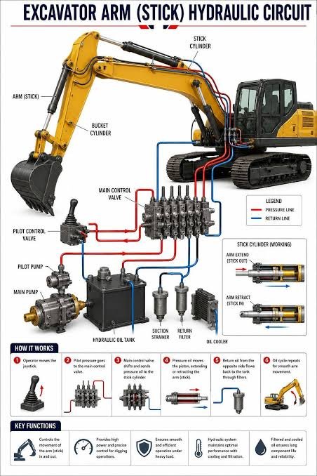
Most hydraulic confusion disappears when you stop seeing individual symbols and start seeing three functional loops. Every excavator hydraulic schematic can be grouped into:
| Circuit | Function | Typical Components | Role in Operation |
|---|---|---|---|
| Main oil circuit | High-pressure main loop | Main pump, main control valve, boom/arm/bucket cylinders, travel and swing motors | Performs the actual work |
| Pilot control oil circuit | Low-pressure control | Pilot pump, joystick/pedal valves, pilot lines to main spools | Issues commands to shift main spools |
| Return & drain oil circuit | Oil recovery | Return filters, tank lines, case drain lines from motors and valves | Returns oil to tank and prevents case pressure |
Remember: the main circuit does the work, the pilot circuit gives orders, and the return/drain circuit cleans up.
Four-Step Reading Method
Step 1: Find the Power Source
Locate the main pumps and pilot pump. Most excavators use two main pumps in series plus an independent pilot pump, all driven by the engine. Follow the pump outlet lines until they reach the main control valve — that valve is the starting point for every circuit.
Step 2: Identify the Main Control Valve and Its Sections
Each section (or “bank”) of the main control valve controls one actuator: boom, arm, bucket, left travel, right travel, or swing. Inside each section you will usually find the directional spool, a pressure compensation valve, and an overload/replenishing valve. Once you know which section feeds which actuator, the schematic begins to read like a flowchart.
Step 3: Trace the Actuators (Cylinders and Motors)
- Cylinders: boom, arm, and bucket cylinders
- Motors: left and right travel motors, swing motor
Follow the valve outlet lines to each cylinder or motor, then trace the return line back to the tank. For gravity-loaded cylinders (especially the boom), pay close attention to the overload replenishing valve — this is a common fault point.
Step 4: Identify the Protective Components
- Relief valve: limits maximum system pressure and vents excess flow
- Overload valve: absorbs shock and protects cylinders/motors from pressure spikes
- Replenishing valve: prevents cavitation by allowing oil into a void under negative pressure
High-Frequency Schematic Symbols
You don’t need to memorize every ISO symbol. Focus on these recurring components:
| Symbol | What It Does | Where You’ll See It |
|---|---|---|
| Check valve | Allows flow in one direction only; blocks reverse flow | Load-holding circuits, pump outlets |
| Relief valve | Opens at a set pressure to protect the system | Near the main pump or main control valve inlet |
| Throttle valve | Restricts flow to control actuator speed | Flow control for swing or travel |
| Pressure compensation valve | Maintains stable flow during combined operations | Inside each main control valve section |
| Pilot pressure-reducing valve | Maintains a fixed low pilot pressure | Pilot supply line from pilot pump |
Using the Schematic for Faster Fault Diagnosis
Veteran technicians often map symptoms to specific circuit areas before checking parts. Use this table as a starting point:
| Symptom | Likely Areas to Check on the Schematic |
|---|---|
| Individual actions normal, compound actions weak | Pressure compensation valve, main pump flow-combining circuit |
| Boom drops too fast or judders | Boom overload replenishing valve (sticking) |
| Excavator pulls to one side during travel | Travel motor, travel overload valve, straight-travel valve |
| All actions are slow | Main pump wear, insufficient pilot pressure |
Tip: Don’t trace every line on the first pass. Start with the main lines, then move to branch circuits, and finally look at protection circuits.
Safety Notes
- Always relieve hydraulic pressure before opening any line or component.
- Refer to the machine-specific service manual for exact pressure settings and test points.
- Use appropriate PPE when working around high-pressure oil: hot oil can cause severe burns.
Conclusion
An excavator hydraulic schematic isn’t a pile of symbols — it’s the machine’s action manual. Once you separate the three circuits and follow the four steps, fault tracing becomes faster and more confident.
For expert help with hydraulic system diagnostics or sourcing new or aftermarket replacement parts, contact Danch Machinery.
About this guide
Published by Danch Machinery as general parts-identification and service-planning information. It is not a signed technical inspection or a machine-specific repair approval. Refer to the sources and scope stated in the article; confirm service procedures and fitment with the current manufacturer documentation for the exact machine.
Machine configurations and service requirements can differ by model, serial number and market. Confirm procedures and fitment with the current manufacturer documentation for your exact machine.